


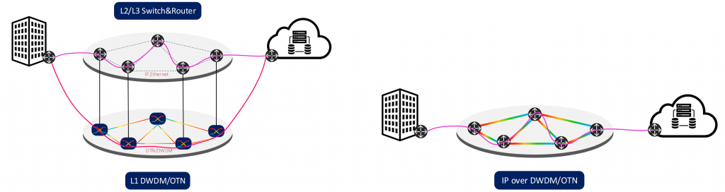
‘Internet Protocol (IP) over DWDM’ is the concept of sending data packets over an optical layer using DWDM for its capacity and other operations. In the modern-day world, the optical layer has been supplemented with more functionality, which was once in the higher layers. This creates a vision of an all-optical network where all management is carried out in the photonic layer. The optical network is proposed to provide end-to-end services completely in the optical domain, without having to convert the signal to the electrical domain during transit. Transmitting IP directly over DWDM has become a reality and is able to support bit-rates of 400Gbps. As we can clearly see, it holds the key to the bandwidth glut and opens the frontier of terabit Internet too.
Some key elements of optical transport performance
Different Fiber Types for Different Applications
| Types | Name | Features | Applications |
| G.651 | Multi-mode progressive index fibre | Application wavelength as 850nm/1310nm | Mainly used in local area networks, not for long-distance transmission. |
| G.652 | Dispersion-unshifted single-mode fibre | The zero-dispersion wavelength is about 1310nm | The most widely used optical fibre. |
| G.653 | Dispersion-shifted optical fibre | Dispersion be minimized at about 1550nm, thus minimizing optical loss | It is very suitable for a long-distance single-channel optical communication system. |
| G.654 | Cut-off shifted optical fibre | 1550nm has the lowest attenuation coefficient(15% less than G.652, G.653, G.655 fibre), so it is called low attenuation fibre, and the dispersion coefficient is the same as G.652 | Mainly used for long-distance transmission under the sea or on the ground. |
| G.655 | Non-zero dispersion-shifted fibre | The dispersion at 1550nm is close to zero, but not zero | Suitable for WDM and long-distance optical cable |
| G.656 | Low slope non-zero dispersion-shifted optical fibre | Attenuation is low between 1460nm and 1625nm, but is too low for a WDM system when the wavelength is less than 1530nm | It ensures transmission performance in the broader wavelength range of DWDM system. |
| G.657 | Bending Insensitive optical fiber | The minimum bending radius is 5-10mm | Mainly used for FTTH access. |
Optical Signal-to-Noise Ratio(OSNR)
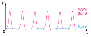
- OSNR is a measure of the ratio of signal level to the level of system noise
- As OSNR decreases, possible errors increase
- OSNR is measured in decibels(dB)
- EDFAs are the source of the noise.
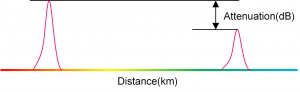
Attenuation
- The attenuation of the optical fibre is a result of two factors, absorption, and scattering.
- Passive media components, such as cables, cable splices, and connectors additionally cause it.
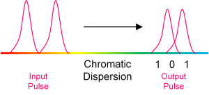
Dispersion
- Material Dispersion occurs because the speed of light varies at different wavelengths through glass
- Waveguide Dispersion is caused because the light is transmitted in the fibre’s mode-field diameter (MFD), which includes the fibre core and the inner part of the cladding.
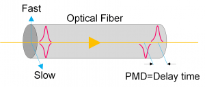
- Even small amounts of glass ovality/non-concentricity or non-concentric stresses in the cable can cause one of the polarizations to travel faster than the other, spreading out in time as they travel along with the fiber. This phenomenon is called polarization mode dispersion (PMD).
Non-Liner Effects
- Polarization Mode Dispersion(PMD)
- Caused by Non-Linearity of Fiber Geometry
- Effective for Higher Bitrates
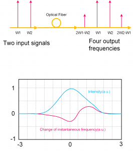
- Four-Wave Mixing (FWM)
- Effects multi-channel systems
- Effects higher bit rates
- Self/Cross Phase Modulation (SPM,XPM)
- Caused by high channel power
- Caused by channel interaction
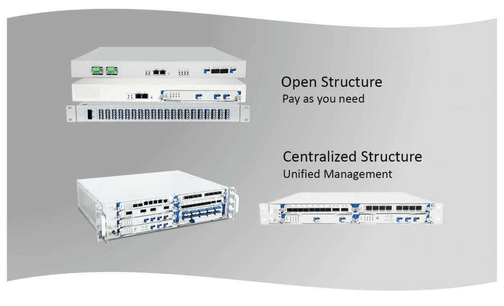
Fiberroad
Optical Transport Network Solution