

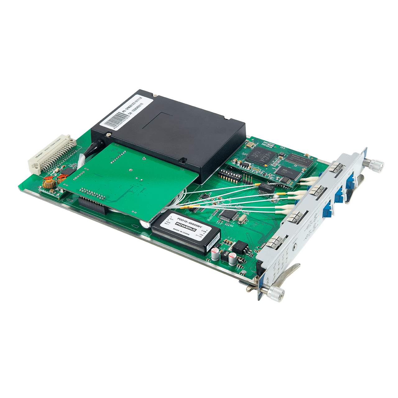
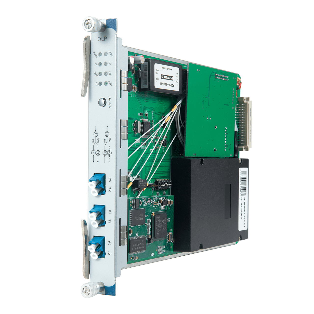
Optical Line Protection Switch
Optical Line Protection Switch is combined of OLP-Optical Line Protection and operation maintainance terminal,it can realize optical power monitoring, optical line auto-switching and network management etc. In optical communication network, OLP monitors optical power of optical fiber and standby optical fiber at real time.In case the current optical power of optical fiber is less than pre-set switching threshold value, then alarm is on and it would switch to standby optical fiber automatically to protect optical transmission system line.Optical Line Protection Switch can provide a protection scheme for all routes and main lines easily with low cost, can protect all networks which needs optical line switching, all these above can make a optical communication network with no-block, high reliability, safety and high anti-disaster strength.
OLP 1:1 and OLP 1+1
There are different types of optical line protection devices for network protection. The most commonly used OLP are OLP 1:1 and OLP 1+1. Both of them require a spare fiber optic path. But they use different methods to secure the optical communication networks.
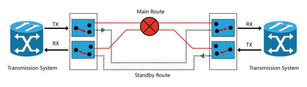
The following picture shows the transmission method of a fiber network deployed with OLP 1:1. The 1:1 optical line protection system uses a selective transmitting and selective receiving mode. There are a main route and a standby route between the two sites. The Tx port is connected to the optical switch inside the OLP device. When there is a fault on the main route, the Rx port will detect the decreasing of the optical power. Then, this OLP 1:1 system will switch the transmitting and receiving businesses from the main route to the standby route. 1:1 OLP system has low insertion loss and support the monitoring of the backup path. In this OLP system the optical fiber for backup path can be used for other business.
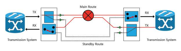
For OLP 1+1, things will be different as shown in the following picture. OLP 1+1 system chooses a mode of dual transmitting and selective receiving. In OLP 1+1, the optical power from Tx are splitted with a split ratio of 50:50 on the main route and the standby route, which means both the main and standby routes are in use no matter whether there is a fault in the main route. While for Rx, the optical signal with better quality will be selected. The advantage of OLP 1+1 system is fast switching and low cost. However, there will be larger insertion loss compared with OLP 1:1 system. This OLP 1+1 system is suggested to be used with short-distance optical lines with large surplus.
OBP (Optical Bypass Protection)
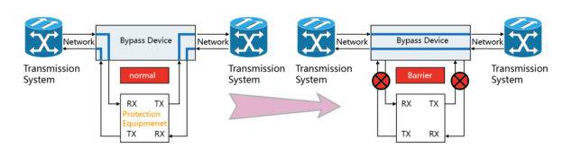
The OLP 1+1 and OLP 1:1 are used to ensure the optical transmission when there are faults in optical fibers. However, some problems of the optical networks are caused by devices that are deployed in the optical network, which will affect the transmission in the whole link. To increase the stability in this situation, optical bypass protection devices are deployed in the network. The following picture shows how the bypass protection device protect the optical line from normal to barrier situation. When there is no optical signal of the device or power down occurs, it will automatically bypass the device, so as to ensure the normal communication.
OLP and OBP Solution
The OLP and OBP systems are both economical solutions to secure our optical network. There are mainly two designs of these devices—plug-in card version and standalone version. The following listed several OLP and OBP for your references.
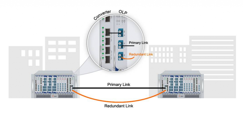
Optical Line Protection Switch Application Example
OTN Systems chassis compatibility
| Part No. | FR-8010 | FR-8015 | FR-8025 | FR-8060 |
| Picture | 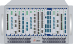 |
|||
| Client Interface | 1U Access, 1-slot | 1.25U Access, 4-slots | 2.5U Access, 7-slots | 6U Access, 15-slots |
| Power Interface | 2-Slots in back panel for power supply modules | 4-Slots in back panel | ||
| Mgmt Interface | Built-in | 1-slot in back panel | 1-slot in front panel | |
| Unit LEDs | Power & In-Use LED’s for each power supply(with use of optional LED module) | |||
| Dimensions(mm) | 430(D)x315(W)x45(H) | 430(D)x365(W)x55(H) | 430(D)x350(W)x114(H) | 430(D)x355(W)x265(H) |
| Power |
Two open bays for Chassis power modules, supporting Universal Input 100-240V VAC, or -48V VDC The dual power supplies can function in instant Fail-Ocer Mode or Load Share Mode |
|||
| Environment | 0~50CHumidity: 5%~95% non-condensing;0-10,000 ft.altitude | |||
| Net Weight | 4.2kg | 4.6kg | 5.2kg | 15.0kg |
Video Gallery
Share This Product
- Reduce interrupt time of communication and improve maintenance efficiency with quickly recovering communication
- Remarkably reduce damage to network caused by fiber failure
- Increase network reliability and improve service quality
- Harmless switch between working path and secondary path and convenient for line overhaul and cutover
- Real-time monitoring power level of fiber
- Support remote control, easy management and maintenance
- Transparent transmission
 |
Parameter | 1:1 | 1+1 | |
|---|---|---|---|---|
| Wor Working wavelength nm | 1260~1610 | |||
| Monitoring Power range dBm | +23~-50 | |||
| Monitoring power accuracy dB | ±0.25 | |||
| Monitoring power resolution dB | ±0.01 | |||
| Return loss dB | ≥55 | |||
| PDL dB | ≤0.05 | |||
| WDL dB | ≤0.1 | |||
| Insertion loss dB | TX<1.2, RX<1.2 | TX<4, RX<1.2 | ||
| Switching time ms | <35 | <15 | ||
| Durability(Life) times | >107 | |||
| Size | OLP Module | 26.5(W)× 195(H)× 252(D) | ||
| Environment | Operating Temperature | -10℃ ~ 60℃ | ||
| Storage Temperature | -40℃ ~ 80℃ | |||
| Relative humidity | 5% ~ 95% Non-condensing | |||
| Power Consumption | ≤15W | |||