

Ethernet OAM is a set of functions that provides a system or network fault indication, performance monitoring, security management, diagnostic functions, configuration and user provisioning. The purpose of these management tools or capabilities is to enable the monitoring and quick restoration of the network in case of failure. Given that a network is typically comprised of equipment owned by different operators and built by many different manufacturers, Ethernet OAM has to be standardized to ensure consistency and interoperability, Ethernet OAM entities are network-aware in that they use information from and provide information to other network entities. They cooperate to provide the consistency and conformity that are critical to an entity’s OAM functions.

Overview of Ethernet OAM
Ethernet OAM mechanisms for server-layer services such as synchronous digital hierarchy (SDH) and for client-layer services-layer OAM and has been developed to support the following functions:
- Monitors Ethernet link connectivity.
- Pinpoints fault on Ethernet networks.
- Evaluate network usage and performance.
These functions help carriers provide service based on service level agreement (SLA). Ethernet operation, administration and maintenance (OAM) are used for Ethernet networks.
Ethernet OAM provides the following functions:
- Fault management
- Ethernet management
Ethernet OAM measures network transmission parameters including packet loss ratio, delay, and jitter and collects traffic statistics including the numbers of sent and received bytes and the number of frame errors. Performance management is implemented on the access device. Carriers use this function to monitor network operation and dynamically adjust parameters in real-time based on statistical data. The process reduces maintenance costs.
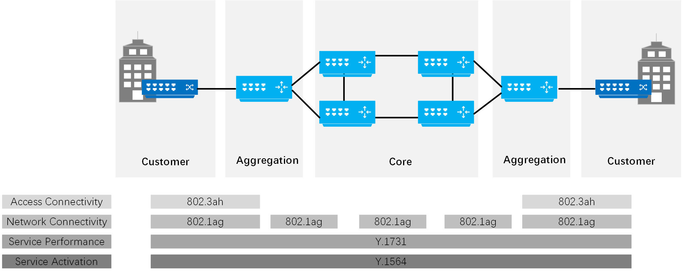
Link-level Ethernet OAM
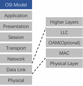
802.3ah (Clause 57 EFM-OAM) defines the Operations, Administration, and Maintenance (OAM) sublayer, which provides mechanisms useful for monitoring link operations such as remote fault indication and remote loopback control. In general, OAM provides network operators with the ability to monitor the health of the network and quickly determine the location of failing links or fault conditions. EFM-OAM described in this clause provides data link layer mechanisms that complement applications that may reside in higher layers.
OAM information is conveyed in slow protocol frames called OAM protocol data units (OAMPDUs). OAMPDUs contain the appropriate control and status information used to monitor, test and troubleshoot OAM-enabled links. OAMPDUs traverse a single link, being passed between peer OAM entities, and therefore, are not forwarded by MAC clients (like bridges or switches).
Provides mechanisms useful for “monitoring link operation”, such as:
- Link Monitoring
- Remote Failure Indication
- Remote Loopback Control
Defines an optional OAM sublayer
Intended for single point-to-point IEEE 802.3 links
Uses “Slow Protocol”1 frame called OAMPDUs which are never forwarded by MAC clients
Standardized: IEEE 802.3ah, clause 57 (now in IEEE 802.3-2005)
IEEE 802.3ah Key Features
OAM Discovery and Link Monitoring
The discovery process is triggered automatically when OAM is enabled on the interface. The discovery process permits Ethernet interfaces to discover and monitor the peer on the link if it also supports the IEEE 802.3ah standard. You can specify the discovery mode used for IEEE 802.3ah OAM support. In active mode, the interface discovers and monitors the peer on the link if the peer also supports IEEE 802.3ah OAM functionality. In passive mode, the peer initiates the discovery process. After the discovery process has been initiated, both sides participate in the discovery. The switch performs link monitoring by sending periodic OAM protocol data units (PDUs) to advertise OAM mode, configuration, and capabilities.
Remote Fault Detection
Remote fault detection uses flags and events. Flags are used to convey the following: Link Fault means a loss of signal, Dying Gasp means an unrecoverable condition such as a power failure, and Critical Event means an unspecified vendor-specific critical event. You can specify the periodic OAM PDU sending interval for fault detection. The switch uses the Event Notification OAM PDU to notify the remote OAM device when a problem is detected.
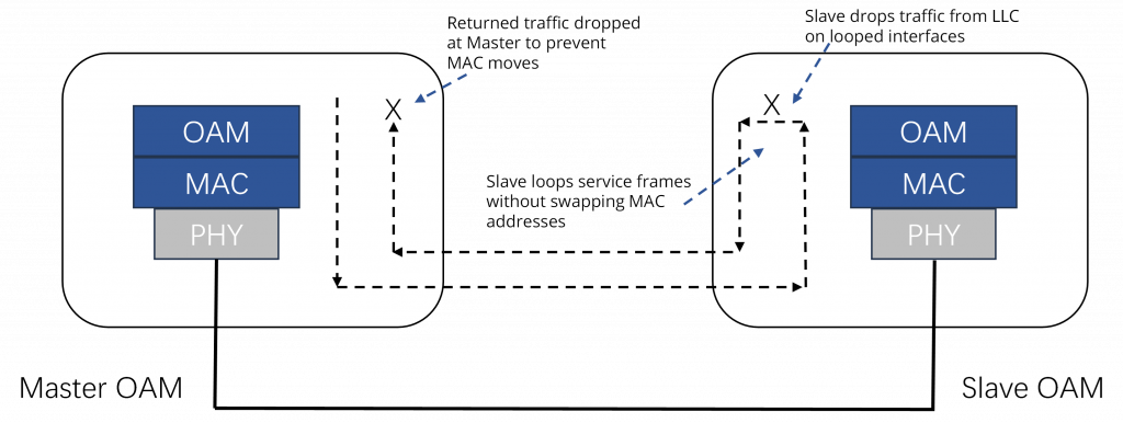
Remote Loopback Mode
Remote loopback mode ensures link quality between the switch and a remote peer during installation or troubleshooting. In this mode, when the interface receives a frame that is not an OAM PDU or a pause frame, it sends it back to the same interface on which it was received. The link appears to be in an active state.
Advanced OAM Features
With the industry’s most comprehensive offering of full features products, Fiberroad’s media converter stands out as “the choice” among industry IT professionals.
Generally, media converters are low-level OSI model devices with no IP or MAC addresses and therefore are transparent to the network. This “transparency” makes them very inexpensive and easy to use but also can make troubleshooting the network very difficult. In an effort to overcome this difficulty and to make media converters ”visible” to network managers, Fiberroad has designed full-featured products to include the most advanced features on the market such as:
- Auto-Negotiation
- Auto MDI/MDIX
- Far-End-Fault
- Link Fault Pass Through
- Transparent Link Fault Pass Through
- Pause
- Remote Management
- Automatic Laser Shutdown
- Automatic Link Restoration
- Port Speed Setting
- Loopback
- Bandwidth Allocation
- Field Upgradeable Firmware
- Source Address Change
- Dying Gasp
- Jumbo Frame
- Cut-Through Mode and Store-and-Forward Mode
- Power over Ethernet
- PRBS
Classes of Fiberroad OAM
| OAM Capabilities | FR-2000 Series | FR-POE332 | FR-6101/4I | FR-6000 Series |
|---|---|---|---|---|
| Basic | ||||
| Auto-Negotiation | √ | √ | √ | √ |
| Auto MDO/MIDX | √ | √ | √ | √ |
| Link Fault Pass-Through | √ | √ | √ | √ |
| Far End Fault | √ | √ | √ | √ |
| Automatic Link Restoration | √ | √ | √ | √ |
| Automatic Laser Shutdown | √ | √ | √ | √ |
| Port Speed Setting | √ | √ | √ | √ |
| Loopback | √ | √ | √ | √ |
| Advance Features | ||||
| Dying Gasp | √ | √ | ||
| RMON Counters | √ | √ | ||
| Bandwidth Allocation | √ | √ | ||
| Field Upgradeable Firmware | √ | √ | ||
| PRBS | √ | |||
| Power over Ethernet | √ | √ | √ | |
| 802.1q VLANs | √ | √ | ||
| Q-in-Q VLANs | √ | √ | ||
| IP addressable | √ | √ | ||
| SNMPv1/v2/v3 | √ | √ | ||
| IEEE 802.3ah Link OAm | ||||
| Discovery | √ | √ | ||
| Dying Gasp | √ | √ | ||
| Link Fault | √ | √ | ||
| Transparent Link Fault Pass Through | √ | √ | ||
| Critical Events | √ | √ | ||
| Remote/Local Loopback | √ | √ | ||
| Fault Isolation | √ | √ | ||
Advance Product Features
Link Fault Pass Through
Link Fault Pass Through is a troubleshooting feature that prevents devices from isolating link failures and it allows end devices to be notified in the event of a loss of link. Link Pass Through provides the device with ability to monitor both the fiber and the copper RX ports for a loss of signal. If a loss of RX signal occurs on one media port, the device will automatically disable the TX signal on the other port. By shutting down the fiber TX port, the link failure is “pass through” to remote and local devices(See diagram below)
- End device automatically notified of link loss.
- Prevents loss of valuable data unknowingly transmitted over an invalid link.
| Supported Models | FR-2000 Series, FR-POE332 | FR-6101/4I, FR-6000 Series |
|---|---|---|
| Configuration Methods |  DIP Switch |
 # #  PC or DIP Switch |
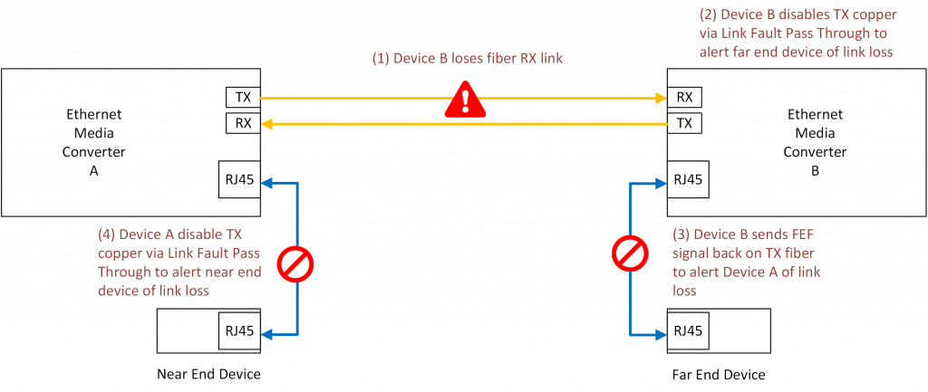
Far-End-Fault
Far-end-Fault(FEF) is a troubleshooting feature that is generally used in conjunction with Link Fault Pass Through to notify both end devices of a loss of link by monitoring the fiber receive(RX) signal. In the event of a loss of the fiber RX signal on the far end, the converter will automatically generate a Far-End-Fault signal and send it on its TX fiber port to notify the near end converter of a fiber link loss. Link Fault Pass Through will then disable the copper links on both ends; alerting both end devices of network trouble(see diagram below).
- Both end devices are automatically notified of link loss
- Prevents loss of valuable data unknowingly transmitted over invalid link
- Allows for quick diagnosis and resolution of network problems
| Supported Models | FR-2000 Series, FR-POE332 | FR-6101/4I, FR-6000 Series |
|---|---|---|
| Configuration Methods | DIP Switch |
# PC or DIP Switch |
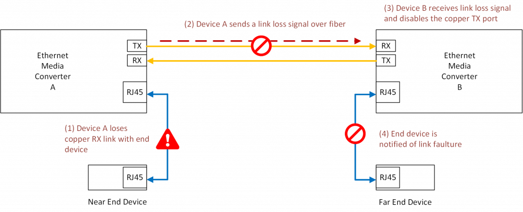
Transparent Link Fault Pass Through
Transparent Link Fault Pass Through will notify an end device of a link failure just like Link Fault Pass Through, however it uses a different method for “Passing Through” this information. Transparent Link Fault Pass Through sends a link loss signal over the fiber, instructing the remote device to shut down the copper port thus notifying the end device, while maintaining the fiber link between the two devices(see diagram below).
- End device automatically notified of link loss
- Fiber link remains up as it carries a loss signal
| Supported Models | FR-2000 Series, FR-POE332 | FR-6101/4I, FR-6000 Series |
|---|---|---|
| Configuration Methods | N/A | # PC or DIP Switch |