

Wavelength Division Multiplexing (WDM), A WDM technology that multiplexes several optical carrier signals onto a single optical fiber by using different wavelengths (i.e., colors) of laser light. This technique enables bidirectional communications over a single strand of fiber, also called wavelength-division duplexing, as well as multiplication of capacity. Transmission from combined sources is separated at a remote location according to the individual wavelengths by de-multiplexing onto multiple fibers. WDM technology is often used to refer to filtering products that perform multiplexing or de-multiplexing.
WDM Technology is divided into three different wavelength patterns: Normal WDM, Coarse WDM(CWDM), and Dense WDM(DWDM).
Normal WDM also referred to as bi-di, simplex, and single stand uses the two normal wavelengths 1310nm and 1550nm on fiber.

Coarse Wavelength Division Multiplexing, CWDM is a specific WDM technology defined by the International Telecommunication Union in ITU-T Recommendation G.694.2 Spectral grids for WDM applications: CWDM wavelength grid. The grid is specified as 18 central wavelengths starting at 1271 nm and spaced 20 nm apart.
Dense Wavelength Division Multiplexing, DWDM is a specific WDM technology defined by the International Telecommunication Union in ITU-T Recommendation G.694.1 Spectral grids for WDM applications: DWDM frequency grid. The grid is specified as the frequency in THz, anchored at 193.1 THz, with a variety of specified channel spacing from 12.5 GHz to 200 GHz, among which 100 GHz is common. In practice, DWDM frequency is usually converted to wavelength. Most DWDM wavelengths in use are found in the C-band, i.e. 1530 – 1565 nm.
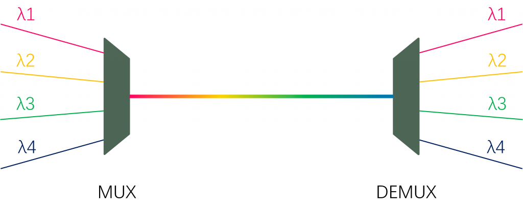
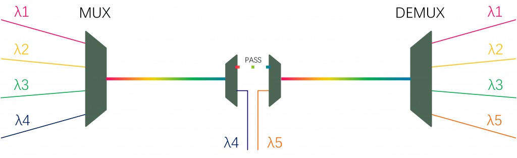
MUX, A WDM filtering product that performs a process of multiplexing or combining two or more optical sources having different wavelengths onto a single fiber.
DEMUX, A filtering product that performs the process of de-multiplexing or separating optical transmission comprised of multiplexed wavelengths onto individual fibers assigned to each wavelength.
Common Port, For a MUX product, combined channels are transmitted from the common port. For a DEMUX, the combined channels are received at the common port.
Expansion or Upgrade Port For CWDM products, there will normally be either an upgrade or an expansion port, but not both. The upgrade or express port on a CWDM MUX or DEMUX is used to add, drop, or pass through additional channels. For instance, on a CWDM MUX side, this port will provide a way to add transmit channels to the fiber circuit. On a CWDM DEMUX side, the expansion or upgrade can be used to pass downstream channels that are not locally DEMUXED. Or, it can also be used to add return channel(s) on a bi-directional circuit span.
For DWDM products, the purpose of an upgrade port is to be able to add, drop, or pass through C-band DWDM channels not already in use, i.e., only channels that reside in the band 1530-1565 nm. If the DWDM product also has an expansion port, then that port is normally used for additional channels residing outside the C-band, such as most of the CWDM channels.
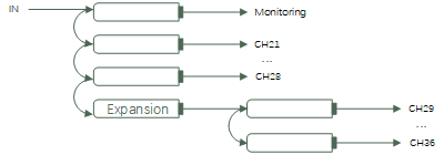
Monitoring Port, WDM products may provide monitoring ports. To monitor a low-power sample of the optical signal occurring at the common port, usually at a 5% or less power level. The monitoring port can also be used to inject an out-of-band signal. If the product has two monitoring ports for the same circuit, the ports will be directional. One port will monitor the transmit signal and the other for the received signal. If the circuit has a single monitoring port, then it is almost always bi-directional and will monitor both transmit and receive optical signals.
Wavelength,In WDM practice, wavelengths such as the wavelength of a communications laser, the wavelength specifications for optical filters, and the wavelengths of optical transmission channels over fiber are all given as λ, the wavelength in nanometers(nm)as would occur in a vacuum.
Center Wavelength, is the wavelength at which a particular signal channel is centered. The International Telecommunications Union (ITU) has defined the standard optical frequency grid (channel center frequency) with 100 GHz spacing based on the reference frequency of 193.10 THz (1552.52 nm), the so-called ITU Grid. Channel center wavelengths are chosen at the wavelengths corresponding to the ITU Grid.
Channel, In WDM practice, a channel is a single and unique transmission at a designated wavelength that may occur along with other channels having different wavelengths. A transmission channel can also refer to the end-to-end physical path. Channel Spacing (GHz), is the frequency difference between two neighboring channel center frequencies in DWDM components or modules. DWDM MUX/DEMUX devices in BaySpec have their channel spacing of 50, 75,100 and 200GHz.
Center Wavelength Offset (pm)is a relative drift of the actual central wavelength of a particular channel concerning the standard ITU Grid. The wavelength drift may result from inappropriate alignment and the design of the optical system.
Channel Pass Bandwidth (nm) is defined as a maximum wavelength (or frequency) range around the corresponding center wavelength (or frequency) at a given power level. Now, the industry well accepts the definition at 0.5 dB down power level. Note that due to the center wavelength offset of a channel the operating channel pass bandwidth may be smaller than that when the center wavelength is accurately at the ITU Grid.
Thermal Wavelength Stability (pm/°C) specifies the maximum wavelength drift of the spectral center of a particular channel due to temperature variation concerning the central wavelength value at the room temperature (23° C).
Pass Band, a specification that gives the range of wavelengths about the nominal, central wavelength of the filter that adheres to the specified insertion loss. In practice, it is the tolerance of the filter for laser drift away from the center wavelength. For example, a typical passband for CWDM filters is ± 6.5 nm about the center wavelength. So a 1551 nm laser could operate within a range of 1544.5 nm to 1557.5 nm without encountering extra channel loss.
Insertion Loss, the loss of signal power resulting from the insertion of a WDM filter in a transmission line or optical fiber and is usually expressed in decibels (dB).
Return Loss, When the optical fiber signal enters or leaves an optical component (such as an optical fiber connector), the discontinuity and impedance mismatch will lead to reflection or return. The power loss of the reflected or returned signal is called return loss (RL). The insertion loss is mainly to measure the result signal value when the optical link encounters the loss, while the return loss is to measure the reflection signal loss value when the optical link encounters the component access.
Polarization Dependent Loss (PDL), The loss exhibited by a WDM filter is dependent on the optical polarization of the light. PDL is the largest difference in maximum insertion loss occurring at all states of optical polarization. PDL for a WDM product is specified as the largest allowed PDL for any channel.
Polarization mode dispersion (PMD) is a form of modal dispersion where two different polarizations of light in a waveguide, which normally travel at the same speed, travel at different speeds due to random imperfections and asymmetries, causing random spreading of optical pulses.
Channel Isolation(dB), is also called far-end crosstalk at a given wavelength that is the ratio of the light intensity at the undesired port to the light intensity at the desired port. So it is a measure of how well different wavelengths are separated at the output of a dense wavelength division demultiplexer.
Non-adjacent Channel Isolation (Non-adjacent Channel Crosstalk) (dB) is the relative amount of unwanted power that occurs in a particular channel passband from the non-adjacent channels. Commonly, only the two first non-adjacent channels (left- and right-hand sides) are accounted for.
Channel Ripple, Ripple is defined as the maximum peak-to-peak variation in dB of insertion loss across a filter passband. WDM product ripple is specified as the largest allowed ripple occurring in any channel.
Directivity (dB) is also called near-end crosstalk that is the ratio of the optical power launched into an input port to the optical power returning to any other input port. In DWDM, directivity is applied to MUX devices only.
Operating Temperature (°C) is the temperature range over which the device can be operated and maintain its specifications.
Storage Temperature (°C) is the temperature range over which the device can be stored without damage and can be operated over operating temperature according to its specifications
Filter Wavelength Division Multiplexer(FWDM), The component combines or separates light at different wavelengths in a wide wavelength range. They offer very low insertion loss, low polarization dependence, high isolation, and excellent environmental stability, High power handling capability can be achieved through unique pigtail processing and high-quality AR coating. These components have been extensively used in optical amplifiers, WDM networks, and fiber optical instruments.
Red/Blue Band Filters, is a thin-film filter component, which is a three-port device. One port is called the “Common”. The other two ports provide the conduit for the two-wavelength “band”. The two bands are the blue(λ<1543nm)and the red(λ>1547nm). One band goes thru the Reflected leg, and the other band goes thru the passing leg.
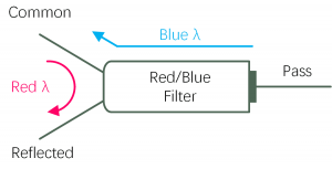
In a DWDM module, which uses a Red/Blue filter, a Mux may be combined with Demux. For example, the Mux combines DWDM channels in the Red nad, while the Demux separates DWDM channels in the Blue Band. Using a Red/Blue filter, one can combine the Red Transmit channels and the Blue Receive Channels onto a single fiber.
Optical add-drop multiplexer (OADM), a device used in wavelength-division multiplexing systems for multiplexing and routing different channels of light into or out of a single-mode fiber (SMF). This is a type of optical node, which is generally used for the formation and construction of optical telecommunications networks. “Add” and “drop” here refer to the capability of the device to add one or more new wavelength channels to an existing multi-wavelength WDM signal, and/or to drop (remove) one or more channels, passing those signals to another network path. An OADM may be considered to be a specific type of optical cross-connect.
Athermal Arrayed Waveguide Grating (AAWG), Dense Wavelength Division Multiplexer (DWDM)based on silica on silicon technology is designed for ITU channel spacing applications where no electrical power is required. It operates at 50GHz or 100GHz channel spacing ITU Grid DWDM wavelengths from 1526nm to 1565nm. The AAWG DWDM can be used to replace the filter-type DWDM Mux DeMux for cases where no power is available. The low cost and high performance make it the ideal solution for metro and long-haul DWDM applications.
Gaussian AWG is the simplest type of AWG design where the individual channel passband shape is described by a Gaussian function. The Gaussian AWGs provide the lowest insertion loss out of all AWG types but requires tighter tolerances on other system components to ensure the peak of the Gaussian curve stays within the passband over the full operational temperature range.
Gaussian Pass Band (nm) specifies a class of DWDM MUX/DEMUX devices whose spectrum profiles within the passband are essentially Gaussian.
Flat-Top Pass Band (nm) specifies a class of DWDM MUX/DEMUX devices whose spectrum profiles within the passband are relatively flat by comparison with the Gaussian profile. A flat-top spectrum profile may be super-Gaussian or ideally box-like.
Compact CWDM is a mini version of CWDM. A wavelength division multiplexing technology based on TFF(Thin Film Filter), which works in the same way as CWDM. The difference is that CCWDM uses free space technology, and its package size is greatly reduced compared with CWDM modules, and insertion loss is lower and more consistent.
Local Area Network Wavelength Division Multiplexing(LWDM), is one of the newest xWDM technologies and use in 100G, 200G, 400G optical links that have been adapted for use in 25G SFP28 transceivers. This innovation provides greater flexibility in network design and enables 5G implementation using available 100G and 200G LAN-WDM transceivers by utilizing LAN WDM wavelengths.
Metro Wavelength Division Multiplexing, also Micro-optic Wavelength Division Multiplexer(MWDM), is based on the 6 wavelengths of CWDM, shifted by 3.5nm left and right to expand to 12 waves, and is one of the cost-effective plans.