

What is Power over Ethernet in Networking?
Power over Ethernet(PoE) is an innovative technology that passes electric power over twisted-pair Ethernet cable to powered devices. Used in homes, offices, and schools, it enables one RJ45 cable to provide data connection and electric power to these other devices instead of a separate cable for each.
PoE is one of the most cost-effective networking technologies available. It allows professionals to install remote or external equipment without connecting to AC power and can deliver power to several locations without having to install additional electrical cables or outlets in each spot. PoE (Power over Ethernet) also makes it easier for companies to expand their networks and respond more quickly.
Choosing the Right Power Over Ethernet Solution

Upgrade your network infrastructure with our powerhouse Gigabit PoE Fiber Media Converter. Our cutting-edge technology ensures lightning-fast data transfer over optical fiber while providing up to 30W of power to connected devices, giving you peace of mind knowing that your network is operating at maximum efficiency. Trust us, you won’t want to miss out on this game-changing device!

The perfect solution for your power-hungry devices, our 24 Port Gigabit Unmanaged PoE Switch delivers reliable and lightning-fast connectivity without the hassle of managing complicated configurations. Designed with network engineers in mind, this switch is ready to handle even the most demanding workloads with ease.
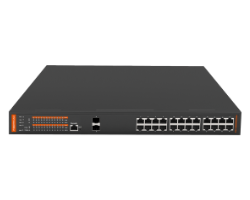
Upgrade your business network with our 24-Port Managed PoE Switch – the ultimate solution for powering multiple devices with ease. With stable and reliable Ethernet connectivity, this switch is a must-have for Network Engineers looking to enhance their system’s capabilities. Trust us to provide a seamless and efficient power source for your wireless APs, IP cameras, VoIP phones, and visual intercoms!
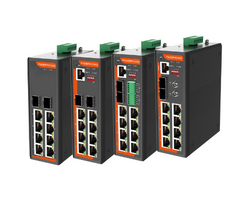
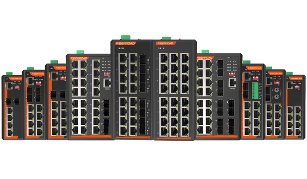
Fiberroad’s Unmanaged/Managed Industrial PoE Switches are the ultimate solution for Network Engineers seeking reliable and robust switches. With a wide range of options available, you’re sure to find the perfect fit for your industrial network needs. Trust in Fiberroad’s quality and expertise to deliver unparalleled performance that keeps your network operating at peak efficiency.
Classes of Power over Ethernet Standard
IEEE 802.3af-2003 standard is commonly known as “PoE”. It defines PoE Classes 0-3, with maximum power at PD being 12.95W.
IEEE 802.3at-2009 standard is commonly known as “PoE+” or “PoE Plus”, and it is the later update to the IEEE 802.3af-2003 “PoE” standard. It defines PoE Classes 0-4, where Classes 0-3 are incorporated from the older 802.3af “PoE” standard under “Type 1”, and “Type 2” only includes Class 4 with maximum power at PD being 25.5W.
IEEE 802.3bt-2018 is named “4PPoE”. It incorporated Classes 0-4 from the earlier standards and added “Type 3” (Classes 5-6) and “Type 4” (Classes 7-8), with maximum power at PD being 71.3W.
PoE Type 1
Name: PoE, 2-pair PoE
Standard: IEEE 802.3af
Maximum port power: 15.4W
‘PoE’ was initially designed to power low-power devices such as IP telephones. In 2003, IEEE 802.3af was standardised to use two of the four twisted pairs of wires in standard (at the time) Cat3 Ethernet wire runs. IEEE 802.3af provides up to 12.95W to powered devices at 37V-57V. There is some loss, so a PoE switch port is generally rated at 15.4W and between 44V-57V. Examples of devices that PoE Type 1 can support include static surveillance cameras, wireless access points and VoIP phones.
PoE Type 2
Name: PoE+, 2-pair PoE
Standard: IEEE 802.3at
Maximum port power: 30W
PoE+ or IEEE 802.3at Ethernet standard, which the Institute of Electrical and Electronics Engineers released in 2009. It delivers up to 30W of power at the port level over an Ethernet twisted pair cable and up to 25.5W of power to each device. It connects higher-powered devices to a network, such as PTZ cameras, video IP phones, and alarm systems. However, because it is backwards compatible, it can support the types of devices typically supported by PoE Type 1 and devices supported by PoE Type 2.
PoE Type 3
Name: PoE++, 4-pair PoE, 4P PoE, Ultra PoE
Standard: IEEE 802.3bt
Maximum port power: 60W
Also known as 4-pair PoE, 4PPoE, PoE++, or Ultra PoE, Type 3 PoE uses all four pairs in a twisted-pair copper cable to deliver power at the PD—unlike Type 1 and 2, which only use two pairs. This higher level of PoE adheres to the IEEE 802.3bt standard, which came out in 2011. It provides up to 60W of power to each PoE port and up to 51W of power to each device. These higher levels of power support devices include multi-radio wireless access points, PTZ cameras, building management devices, and video conferencing equipment. It supports Cat5 cables or better.
PoE Type 4
Name: Higher-Power PoE, PoE++
Standard: IEEE 802.3bt
Maximum port power: 100W
Commonly known as Higher-Power PoE, Type 4 PoE offers the highest power capabilities of all existing PoE types. This PoE type helps satisfy the growing power requirements of network devices and IoT. Conforming to the newest IEEE 802.3bt standard, Type 4 PoE delivers 90W of power from the PSE and up to 70W of input power at the PD to each device. However, it has the potential to supply a maximum of 100W of power per port if necessary. Due to the high quantities of power that it produces, Type 4 PoE can support extremely power-hungry devices such as laptops and flat screens.
Power over Ethernet PSE Types
There are three main types of PSE (Power Source Equipment) in use today; all are compatible with Cat5e or higher category cable. PSE type is chosen based on the existing infrastructure and the number of connected PoE devices.
- Network Switch and Fiber Media Converter
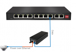
A Power over Ethernet (PoE) Switch is a device that can supply power to devices over an Ethernet cable. It can be used to power devices such as IP phones, Wireless Access Points, and Security Cameras. A PoE switch can also be used to connect devices that are not PoE-compliant by using a PoE Injector.
A PoE Fiber Media Converter combines power and data on one cable offering copper-to-fibre connectivity while providing Power to PD. The PoE media converter offers an economical path to extend the transmission distance of an existing network.
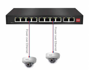
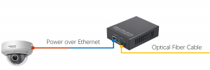
Figures 2 & 3, PoE Switch and PoE Media Converter
- Single-Port Injector(Midspan)
A Single-Port PoE Injector (Midspan) is designed in line with an Ethernet cable to provide power to one device. It suits applications where you don’t have enough poe ethernet devices or if the data needs to be transmitted a long distance before being converted back to copper cabling and then applying power.
The downside to using a Single-Port PoE Injector is the requirement for a mains outlet to operate and the tendency to become costly when more than a few devices require power.
Power over Ethernet Negotiation
Power over Ethernet (PoE) negotiation is the process of determining if and how much power should be provided to a device over an Ethernet cable. This is typically done through a special signalling protocol between the power source (usually a PoE switch) and the device that is to receive power (known as a PD, or Powered Device). If both the PoE switch and PD support the same PoE standard (such as IEEE 802.3at), then they can negotiate to provide the PD with up to the maximum amount of power specified by that standard. However, if the PoE switch and PD do not support the same standard, they must negotiate to provide the PD with a lower amount of power. PoE negotiation aims to ensure that only as much power as is needed is provided to the PD. This helps to avoid potential problems such as overloads and electrical hazards. It also helps to conserve energy, since devices that do not need a lot of power can be powered by lower-power PoE standards.
The negotiation comprises three stages: discovery, classification and operation.
Discovery
PSE leaves the Ethernet port unpowered and periodically checks if something has been plugged in. The low voltage used during detection is unlikely to damage a device not designed for Power over Ethernet. When a PD is connected to the PSE’s port, the PSE detects this and carries on to the classification stage.
PoE Classification
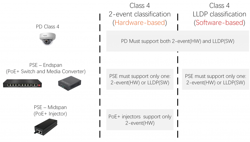
Classification is the process by which the PSE determines whether the connected device requires Power, if so, what class of PoE Power it requires. Classification may happen in a 1-event or 2-event form, depending on the PoE class of the PD.
1-event classification – for PDs of 802.3af/at Class 0-3
PSE sends a single voltage impulse to the PD, reads the current value on the wire, checks what PoE class this current value corresponds to, and provides power accordingly. If the PD returns Class 1, 2 or 3 values, the PSE provides Class 1, 2 or 3 power, respectively. If PD returns a Class 0 value, Class 3 power is supplied.
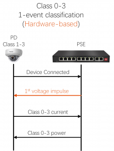
Figure 5: 1-event classification
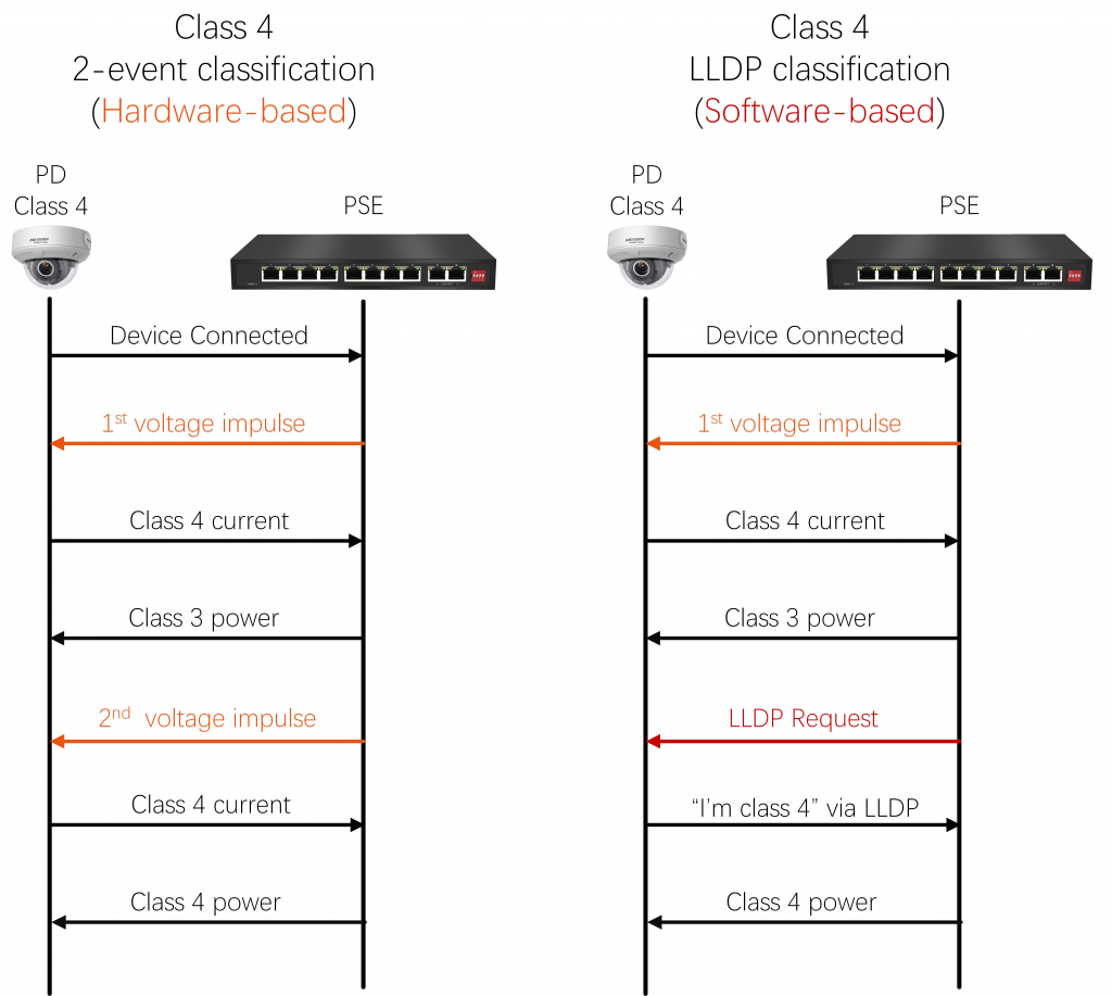
2-event classification – for PDs of 802.3at Class 4
When the PD is identified as a Class 4 device, the PSE will use a second event to verify that the PD really needs a higher level of power. This second event can be either of the two following methods:
Hardware-based 2-event classification
PSE first performs 1-event classification as described above. If it reads the Class 4 current value from the PD, it only supplies Class 3 power and repeats the voltage impulse for the second time. If after this 2nd event it is confirmed that the PD is Class 4, the PSE provides Class 4 power to the PD.
Software-based LLDP classification
PSE first performs 1-event classification as described above. If it reads the Class 4 current value from the PD, it only supplies Class 3 power and requests confirmation from the PD via Layer 2 LLDP protocol on whether the PD is indeed Class 4. If after this 2nd event it is confirmed that the PD is Class 4, the PSE provides Class 4 power to the PD.
2-event classification support
The IEEE 802.3at standard defines that Class 4 PDs must support both hardware-based 2-event and software-based LLDP classification, while PSE must only support one but may support both. PoE+ injectors typically only support hardware-based 2-event sort. Many PoE+ switches support both methods.
PoE Power Supply Budget Calculation
Calculating the power budget for a Power over Ethernet (PoE) network can be tricky. There are a lot of factors to consider, and if you’re not careful, you can easily end up overspending on your power supply. To help you calculate your PoE power budget, we’ve put together this handy guide. We’ll walk you through all the factors you need to consider and show you how to use our free PoE power budget calculator.
Step1: Add Up The Demand For PoE In Watts
The total expected power demand from all your PDs should be calculated. It should include the maximum power and upper limits for each classification of PD. Any unspecified devices should be considered Class 0.
For example, IEEE802.3af devices can consume 9 watts; however, as they’re Class 0 devices, you can assume they consume 15.4 watts.
Round the number up occasionally so that the cable used to connect the PD and PoE switch doesn’t wear out too quickly.
For example, a typical IEEE802.3at Class 4 IP camera consumes 25.5 watts. This round of 30+ watts gives you a buffer if there is an unavoidable loss between the PoE switch and your device.
One of the most important considerations when choosing a PoE power budget is making sure there are ports available in your design. Remember, having at least one spare port on the PD device can be handy for diagnostics or troubleshooting purposes. And some clients may even want extra ports to provide them with the option of adding more PD devices in the future. But don’t worry – just as long as you select appropriate PD devices and integrate them correctly, accounting for spare ports isn’t necessary as part of a PoE power budget calculation.
Step 2: Scale For The Operating Environment
If you perform a power budget calculation, you have to take into account the environmental conditions.
The rate at which a power supply is designed to lose its capacity over time will depend on the conditions it is used under. The company says that in favourable or controlled conditions, you can expect the long-term performance of a power supply to be 70% of its rating. Under this sort of environment, you should divide the total wattage from step one by 0.7.
Every part of the power supply is engineered to be resistant to heat, cold and moisture. However, these factors can change performance and lifetime. Divide the total wattage from step one by 0.6 for this kind of setting.
Electrical installations operating in extreme conditions often necessitate industrial-grade equipment. Fiberroad Industrial PoE series, for example, is a DC 48VDC power supply that is built to withstand years of exposure to high levels of noise and vibration in the field.
Take this harsh scenario, for instance:
The switch and power supply will be installed in a metal enclosure exposed to direct sun, at a site in the northeastern United States. In winter, the temperature inside the enclosure could be as low as –10°F/–24°C. And in summer, it could be as high as 140°F/60°C. Considering this inflexion with temperature, we expect the power supply to operate at 60% capacity.
In order to calculate which power supply you need, you’ll need to know how much power your computer will draw in total. If the current equation is X, and the anticipated long-term performance drop is 50%, then simply multiply X by 0.5.
Step 3: Select The Power Source
When considering the needs of your PoE power supply, it’s important to take into account the amount of power needed and the environment. We have supplied ratings starting at 30 watts and going up to 720 watts.
Power over Ethernet Cabling
In modern networks, power electronics devices supply power to PDs over the same cabling that is used for data. Cat5e or higher category cable is suitable for IEEE 802.3af and IEEE 802.3at compliant devices.
Any Ethernet cable run from the PoE network switch to the PD should be no more than 328 ft in length, even if a midspan device is located on the line. The midspan PoE injector should be viewed as a patch panel connection. If 328 ft is exceeded, power provision and data communication can be negatively impacted.
Nevertheless, AI Extend is becoming increasingly popular among Power over Ethernet devices, which can extend PoE distance up to 250m. Fiberroad AI Power over Ethernet series supports this function by DIP Switch, whenever turned on as needed. The AI Extend feature is suitable for situations where your power source is too far away. However, that bandwidth limitation is to be aware of.
| 10/100BASE-TX (802af/at, Mode A) |
10/100BASE-TX (802.3af/at, Mode B) |
1000BASE-TX (802.3af/at, Mode A) |
1000BASE-TX (802.3af/at, Mode B) |
1000BASE-TX (802.3bt) |
||||||
|---|---|---|---|---|---|---|---|---|---|---|
| Pin | Data | Power | Data | Power | Data | Power | Data | Power | Data | Power |
| 1 | Rx + | DC + | Rx + | TxRx A + | DC + | TxRx A + | TxRx A + | DC + | ||
| 2 | Rx – | DC + | Rx – | TxRx A – | DC + | TxRx A – | TxRx A – | DC + | ||
| 3 | Tx + | DC – | Tx + | TxRx B + | DC – | TxRx B + | TxRx B + | DC – | ||
| 4 | Unused | DC + | TxRx C + | TxRx C + | DC + | TxRx C + | DC + | |||
| 5 | Unused | DC + | TxRx C – | TxRx C – | DC + | TxRx C – | DC + | |||
| 6 | Tx – | DC – | Tx – | TxRx B – | DC – | TxRx B – | TxRx B – | DC – | ||
| 7 | Unused | DC – | TxRx D + | TxRx D + | DC – | TxRx D + | DC – | |||
| 8 | Unused | DC- | TxRx D – | TxRx D – | DC – | TxRx D – | DC – | |||
Table 2: Lan Port Data and Power Pinout
Notes:
- Power must only be applied in one mode at a time, and the PSE makes this decision. The PSE can support mode A or B, or both. Typically, the method selected is not a concern for an end-user because it is a requirement of the IEEE 802.3af/at standards that all PDs must support both modes.
- With Mode B, the phantom power technique allows the powered pairs also to carry data in 10/100 Mbit/s Ethernet.
- Both Modes A and B are supported in Gigabit Ethernet. The phantom power technique is utilised for both modes, as in Gigabit Ethernet, all four pairs are used for data transmission.
- IEEE 802.3bt “4PPoE” uses all for pairs to provide power in Gigabit Ethernet, hence the name of the standard – 4PPoE (“4-pair Power over Ethernet”).